Engineers and designers are in the business of solving problems. Whether designing a new bridge, a home electronic device, or a satellite communications system, engineers use a common way of thinking called the systems approach.
A system is a collection of components that work together to perform a function. All systems — no matter how simple or complex — can be described using the same basic structure:
This is called the universal system diagram. The word "universal" means it can be used for any situation at all.
Input — what goes into the system to make it work (e.g. electricity, a signal, a physical force)
Process — what the system does to the input
Output — what comes out of the system (desired outputs and unwanted outputs)
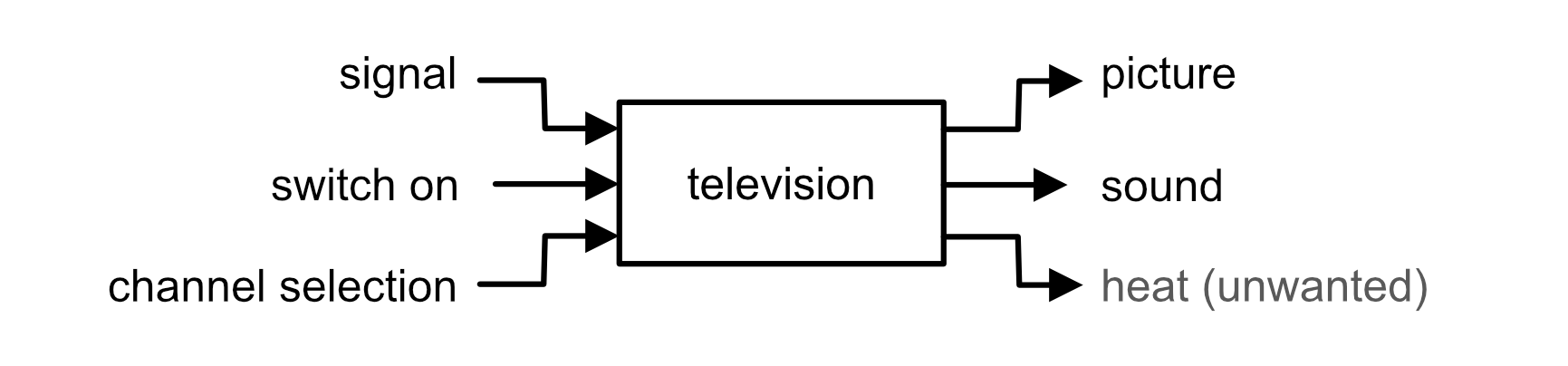
Worked Example — Universal system diagram: Television
A television receives a broadcast signal, is switched on by the user, and the user selects a channel. It outputs picture, sound, and heat as an unwanted output.
📌
Diagram coming soon — systems-universal-tv.png
Add this file to the images/ folder to display it here.
⚠️ Do not include electricity as an input in systems diagrams — electricity is part of the system, not a real-world input. Instead write the real-world input that triggers the system (e.g. "light", "heat", "signal").
✏️ Task 1 — Universal systems diagrams
For each device below, fill in the inputs and outputs (including any unwanted outputs) to complete the system diagram.
Inputs
KETTLE
Outputs (wanted + unwanted)
Inputs
TOASTER
Outputs (wanted + unwanted)
Inputs
RADIO
Outputs (wanted + unwanted)
Inputs
WASHING MACHINE
Outputs (wanted + unwanted)
Inputs
3D PRINTER
Outputs (wanted + unwanted)
Inputs
FIRE ALARM
Outputs (wanted + unwanted)
Section 2: Sub-Systems Diagrams
The universal system diagram tells us what goes in and what comes out — but not how it works inside. The next step is to divide the process box into its sub-systems, showing how each part of the system interacts.
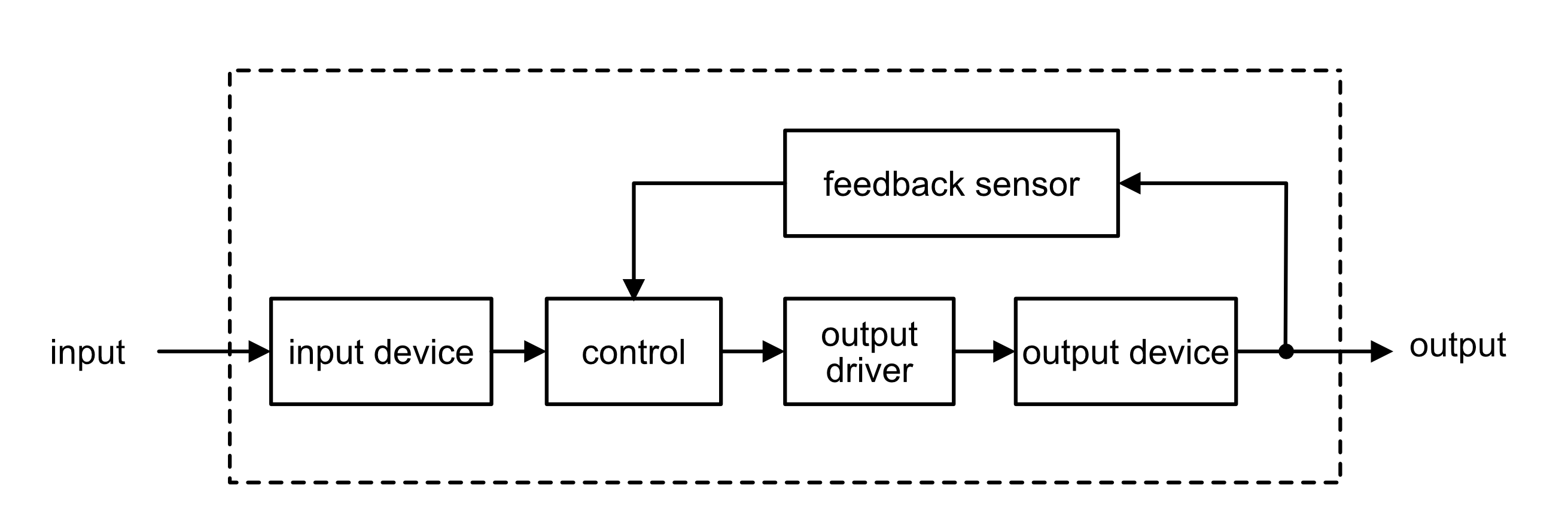
A sub-systems diagram shows all the individual components inside the system boundary, each in its own box, with arrows showing how signals or energy flows between them.
Key terms
System boundary — a dashed line enclosing all the sub-systems. Real-world inputs and outputs are outside the boundary.
Input device (sensor) — converts a real-world input into an electrical signal. Examples: thermistor, microphone, switch, light sensor.
Output device (actuator) — converts an electrical signal into a real-world output. Examples: motor, loudspeaker, LED, heater.
Output driver — an electronic component that boosts a low-power control signal from the control unit to provide the higher current or voltage required to operate an output device such as a motor or heating element. Every output device needs a driver (e.g. transistor, relay).
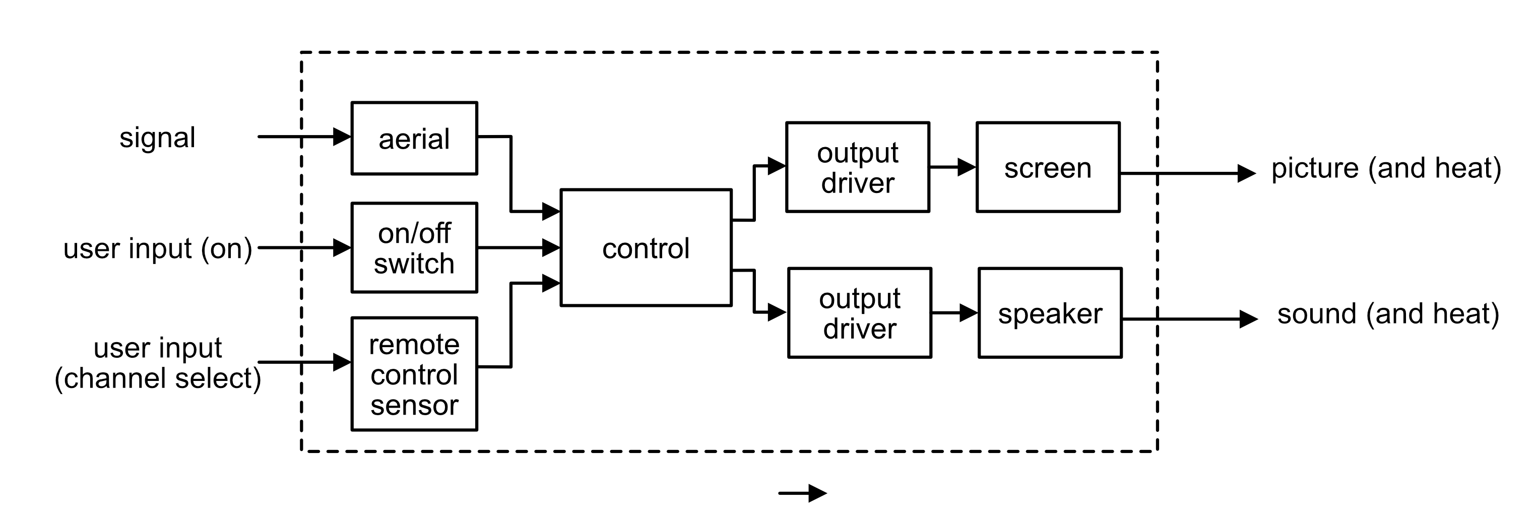
Worked Example — Sub-systems diagram for a television
The television has three real-world inputs: a broadcast signal, user input via a remote control, and user input via the on/off switch. The outputs are picture (along with light and heat) and sound.
📌
Diagram coming soon — systems-subsystem-tv.png
Add this file to the images/ folder to display it here.
✏️ Task 2 — Sub-systems diagrams
1. Draw a sub-systems diagram for a mobile phone. Include: screen, touch pad, control unit, on/off switch, aerial, battery, speaker, microphone, headphone jack, output driver. Show the system boundary and label all connections.
Sketch or describe your diagram ✓ Saved
2. Draw a sub-systems diagram for an electric oven. Include: output driver, heating element, on/off switch, temperature selector switch, fan selector switch, oven light.
Sketch or describe your diagram ✓ Saved
3. For each system below, identify the input device and output device, then describe how the system works by explaining the function of each sub-system in order.
a) Toaster — input device: timer switch | output device: heating element
Description ✓ Saved
b) Greenhouse watering (irrigation) system — input device: moisture sensor | output device: water pump
Description ✓ Saved
c) Factory press machine — input device: push button | output device: motor / solenoid
Description ✓ Saved
Section 3: Open-Loop and Closed-Loop Control
Any system must have some way to control its operation. Systems can also be described as open-loop or closed-loop.
Open-loop control
In an open-loop system, the output simply switches on or off when a certain input happens. There is no feedback — the system does not monitor its output. Once activated, it stays on until switched off.
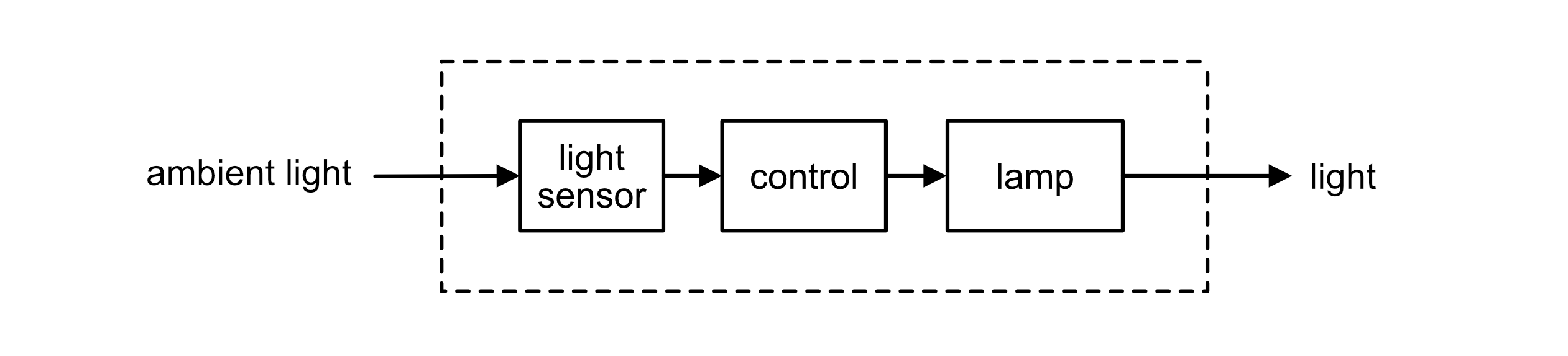
Worked Example — Open-loop control: Automatic street light
An automatic street light uses a light sensor to detect when it gets dark. When the light level drops below a set threshold, the light sensor triggers the control unit, which switches on the LED array via an output driver. There is no feedback — the system cannot detect whether the light is actually illuminating the street. It simply switches on when dark and off when light returns.
📌
Diagram coming soon — systems-open-loop.png
Add this file to the images/ folder to display it here.
Closed-loop control
In a closed-loop system, the output is continually monitored and fed back to adjust the process. This makes the system far more accurate. The feedback signal is compared to the desired value and the system corrects itself automatically.
📌
Diagram coming soon — systems-closed-loop.png
Add this file to the images/ folder to display it here.
Open-loop systems
Simple to design and cheap to build
No feedback — cannot correct errors
Output may drift from desired value
Examples: toaster, street lamp timer, microwave oven
Closed-loop systems
More complex and expensive
Feedback allows automatic correction
Output is maintained at the desired value
Examples: thermostat, cruise control, hair straighteners with automatic temperature control
Open-loop vs closed-loop: summary
Type
Feedback?
Example
Open-loop
No
Street light activated by a light sensor — switches on when dark, no monitoring of output
Closed-loop
Yes — sensor monitors the output
Car cruise control, central heating thermostat, oven temperature control
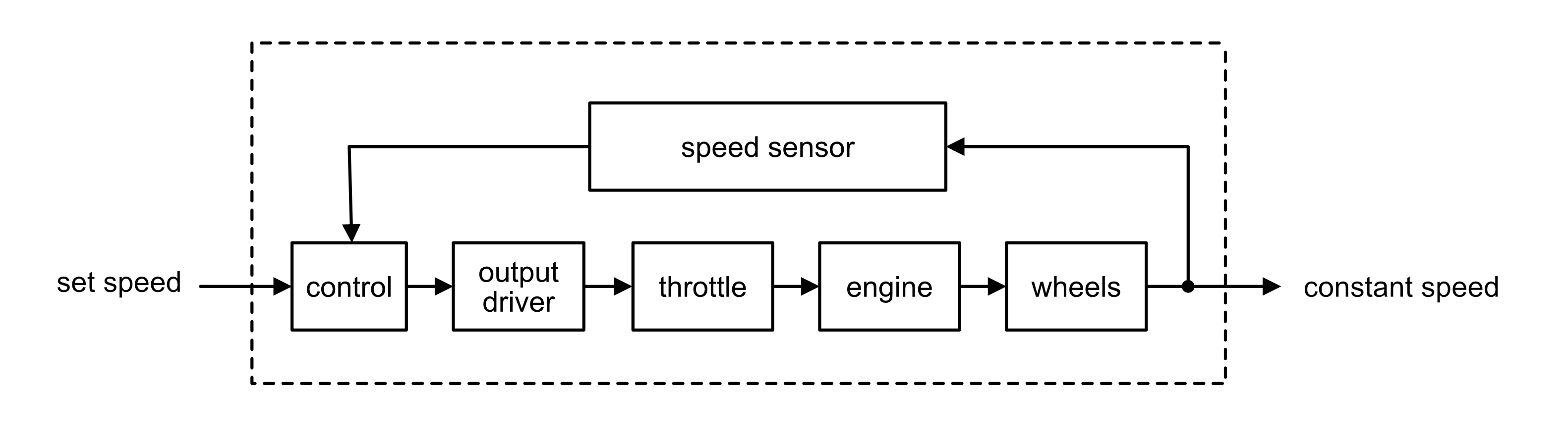
Worked Example — Closed-loop control: Car cruise control
The driver sets a desired speed. A speed sensor (tachogenerator) continuously measures the actual vehicle speed and feeds this back to the control unit. If the actual speed differs from the set speed, the output driver adjusts the throttle to correct it. The system constantly monitors and corrects, keeping the speed accurate.
📌
Diagram coming soon — systems-cruise-control.png
Add this file to the images/ folder to display it here.
✏️ Task 3 — Open and closed-loop control
1. State one difference between an open-loop and a closed-loop control system.
Answer ✓ Saved
2. State whether each of the following is open-loop or closed-loop control.
a) A microwave oven set to run for 2 minutes.
Answer ✓ Saved
b) Car cruise control that maintains a set speed.
Answer ✓ Saved
c) Hair straighteners with automatic temperature control.
Answer ✓ Saved
d) A security light on a timer that switches on at 6pm every evening.
Answer ✓ Saved
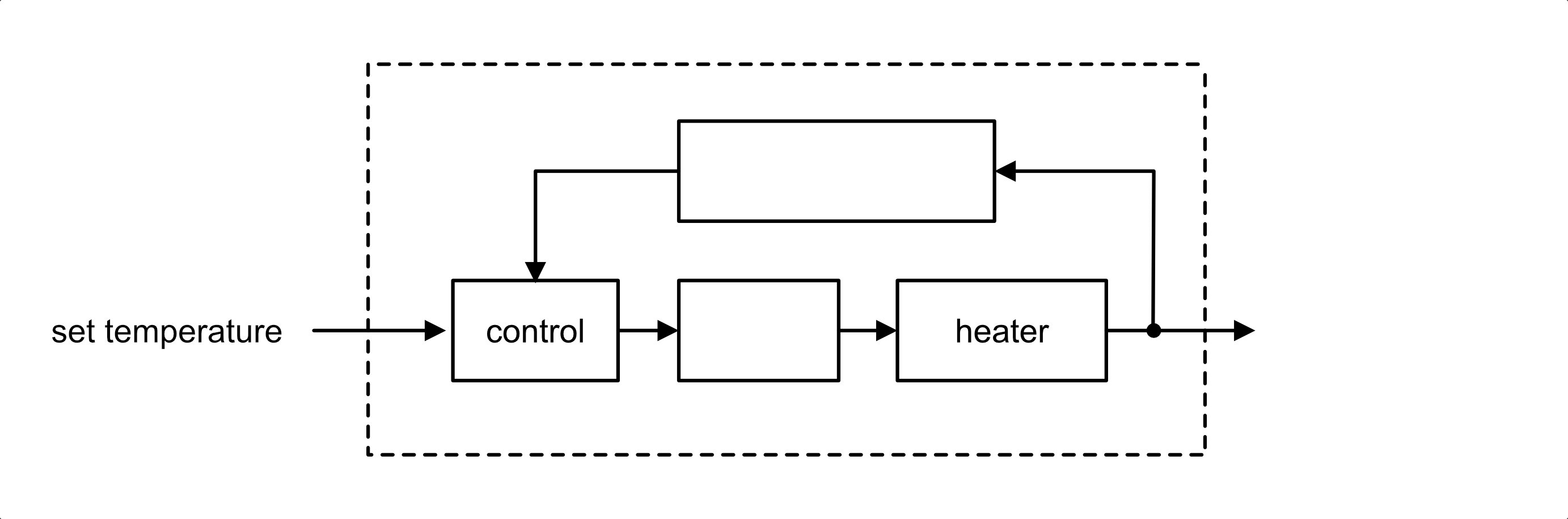
3. The diagram shows a closed-loop control system for a central heating system. Name the three missing sub-systems by clicking each orange box and typing your answer.
📝 Exam & assignment tip: Every line in a sub-systems diagram must have an arrowhead — including both lines into and out of the feedback sensor. The feedback line must always be taken from after the output device, not from the device itself.
a) Name the sub-system that provides the feedback signal.
Answer ✓ Saved
b) What does the feedback signal tell the control unit?
Answer ✓ Saved
c) What action does the control unit take if the room temperature falls below the set value?
Answer ✓ Saved
4. Draw a closed-loop control diagram for a refrigerator that automatically maintains a set temperature. Include: temperature sensor, control unit, output driver, compressor. Show the system boundary and clearly mark arrowheads on both lines of the feedback loop. Remember: the feedback line must come from after the output device.
Control diagram ✓ Saved
Section 4: Case Study — Domestic Appliances
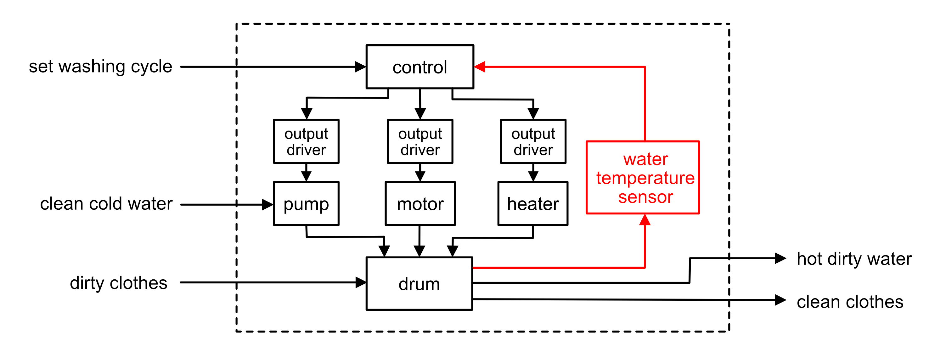
Many everyday appliances use systems principles. The washing machine is a good example of a system with multiple levels of control complexity.
Washing machine
A washing machine is a complex system with both open and closed-loop elements. The wash programme (timer, spin speed) is essentially open-loop — it runs a fixed sequence regardless of outcome. However, the water heating uses closed-loop control — a temperature sensor monitors the water temperature and feeds back to the control unit, which switches the heater on or off to maintain the correct washing temperature.
Worked Example — Closed-loop control: Washing machine water heating
The user sets a washing programme and temperature. The control unit switches the heater on via the output driver. A water temperature sensor continuously monitors the water and feeds back to the control unit. When the target temperature is reached, the control unit switches the heater off. If the temperature drops, the heater switches back on. This feedback loop maintains the correct temperature throughout the wash.
📌
Diagram coming soon — systems-washing-machine.png
Add this file to the images/ folder to display it here.
✏️ Task 4 — Domestic appliances
1a. Sketch a sub-systems diagram for a clothes iron with automatic temperature control. Include a temperature selector, control unit, output driver and heating element. Show the system boundary and any feedback path.
Sub-systems diagram ✓ Saved
1b. Is the iron an open-loop or closed-loop system? Explain your answer with reference to your diagram.
Answer ✓ Saved
1c. Sketch a sub-systems diagram for a slow cooker with a temperature control setting. Show the system boundary, inputs, outputs and all sub-systems inside the boundary.
Sub-systems diagram ✓ Saved
2a. State the name of the sub-system in the washing machine that provides feedback for temperature control.
Answer ✓ Saved
2b. Describe, with reference to the sub-systems diagram above, how the water heating system in the washing machine operates. Mention how each sub-system interacts, and the role of feedback.
Description ✓ Saved
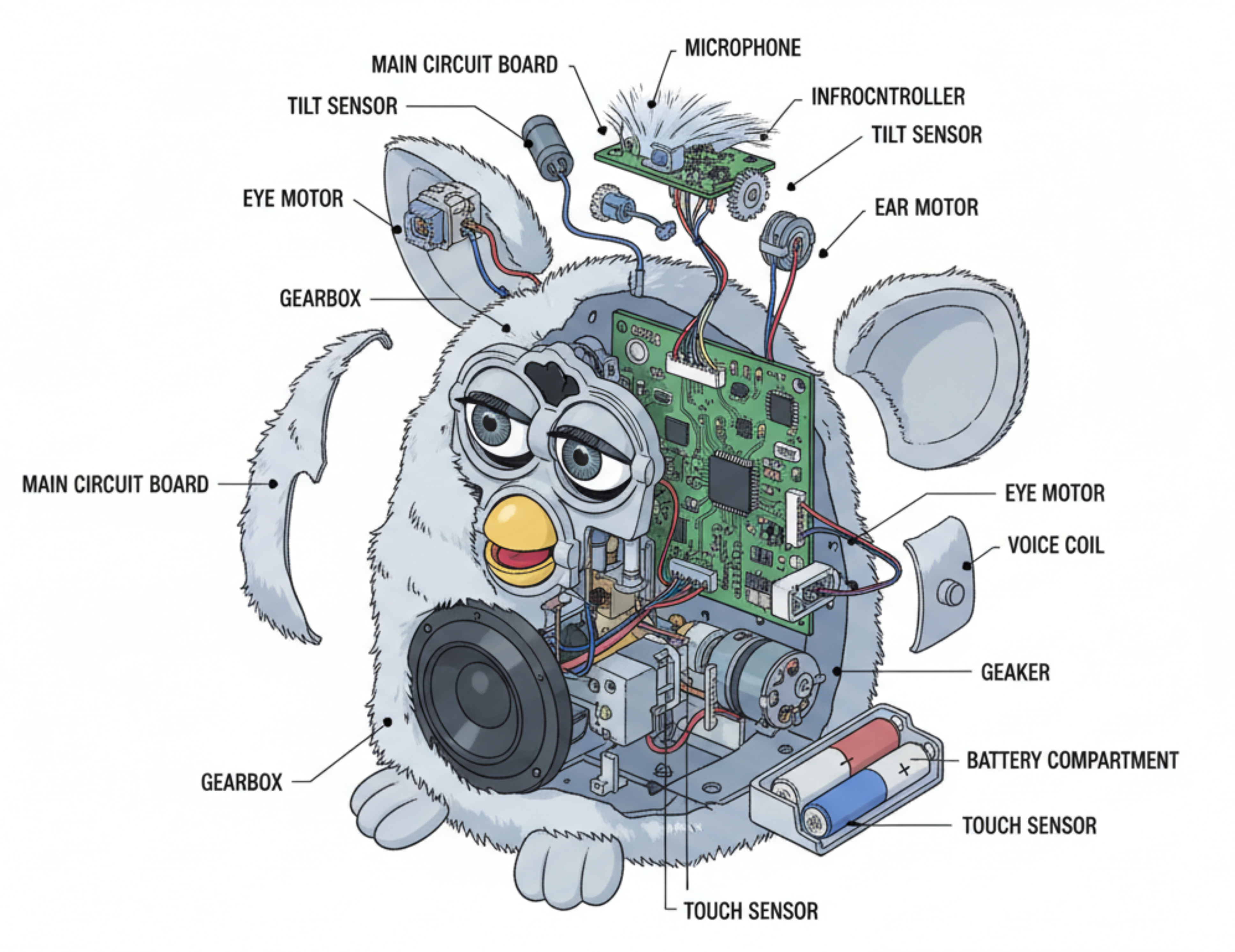
Section 5: Case Study — The Furby Electronic Toy
The Furby is a good example of a mechatronic system — one that uses an electronic circuit to control a number of mechanisms. It contains several sensors so it can react to changes in its environment (e.g. being placed in a dark room or turned upside down).
✏️ Task 5 — Furby case study
1. Research the Furby mechatronic toy and briefly describe how it works as a system.
Description ✓ Saved
2. List the input devices for the Furby and state the function of each. (Hints: push switches on front and back, switch in mouth, light sensor, tilt sensor)
Input devices ✓ Saved
3. List the output devices for the Furby. (Hints: speaker, motor for moving parts)
Output devices ✓ Saved
4. Draw a sub-systems diagram for the Furby. Show the system boundary and make clear the difference between real-world inputs/outputs and system sub-systems.
Sub-systems diagram ✓ Saved
5. Describe how the system works, referring to all sub-systems and how they interact to perform each function.
Description ✓ Saved
💾 Answers saved automatically in this browser on this device.