Mechanisms are devices that convert one motion or force into another. They can be simple — like door handles, scissors and light switches — or complex, as used in industrial robots, cars and bikes.
Mechanisms play a vital role in industry. Most industrial processes have electronic control systems but rely on the movement of mechanisms to do work: pressing large steel sheets, lifting components and cutting material.
All mechanisms: involve motion • involve force • should make a job easier • need an input to work • produce an output.
Types of motion
There are four basic kinds of motion:
🔄
Rotary
Turning in a circle.
e.g. wheels, clock hands, gears
➡️
Linear
Movement in a straight line.
e.g. paper trimmer, lift moving between floors
⇄
Reciprocating
Backwards and forwards in a straight line.
e.g. sewing machine needle, car engine piston
Oscillating
Swinging backwards and forwards in an arc.
e.g. clock pendulum, playground swing
✏️ Task 1 — Types of motion
Complete the table by clicking each cell to mark the correct type(s) of motion for each activity. Click once to tick, click again to clear.
Activity
Rotary
Linear
Reciprocating
Oscillating
Playground swing
100m sprint
Pedalling a bike
Bungee jump
Playground see-saw
Curling stone
💾 Tick selections saved automatically in this browser.
List as many machines or tools from your school's practical rooms as you can for each type of motion.
Rotary:
Answer ✓ Saved
Linear:
Answer ✓ Saved
Reciprocating:
Answer ✓ Saved
Oscillating:
Answer ✓ Saved
Section 2: Gears
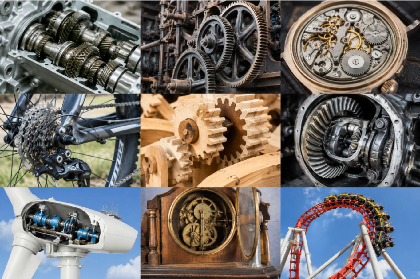
Gears are toothed wheels designed to transmit rotary motion and power from one part of a mechanism to another. They are used to increase or decrease output speed, and can also change the direction of rotation. The most common type is the spur gear.
Real-life example: The gears inside a bicycle's rear hub, an electric screwdriver, or a mechanical clock all use spur gears to change speed and direction.
📌
Diagram coming soon — gear-real-life-examples.png
Add this file to the images/ folder to display it here.
Simple gear trains
When two or more gears mesh together they form a gear train. The input gear is called the driver; the output gear is called the driven. The teeth on the driver effectively push the teeth on the driven gear.
Meshing gears rotate in opposite directions. If the driver is clockwise, the driven is anticlockwise.
Click ▶ RUN SIM to start. The sim shows a 24-tooth driver meshed with a 12-tooth driven gear. Notice the driven gear rotates in the opposite direction and at twice the speed of the driver. The floating labels show RPM and direction for each gear.
NoGrind Sim V1.2 — Peter Strain, Bearsden Academy
If gear A (driver) has 24 teeth and makes one full revolution, its 24 teeth pass the contact point. This pushes gear B around — and because gear B only has 12 teeth, it makes two complete revolutions for every one of gear A.
The gear equation
TeethIn × TurnsIn = TeethOut × TurnsOut
Turns can be revolutions per second (rev s−1) or per minute (rev min−1)
Worked Example 1 — Calculate the output speed
A driver gear has 48 teeth and rotates at 10 rev s−1. The driven gear has 20 teeth. Calculate its speed.
1
Write the equation: TeethIn × TurnsIn = TeethOut × TurnsOut
2
Substitute: 48 × 10 = 20 × TOut
3
Solve: TOut = (48 × 10) ÷ 20 = 24 rev s−1
Worked Example 2 — Calculate the number of teeth
A motor gear has 36 teeth and rotates at 380 rev s−1 clockwise. The driven gear rotates at 152 rev s−1. How many teeth does the driven gear have?
1
36 × 380 = TOut × 152
2
TOut = (36 × 380) ÷ 152 = 90 teeth
✏️ Task 2 — Simple gear train calculations
Calculate the missing quantity in each gear train. Build them in NoGrind to check your answers.
a) Driver: 45 teeth, 20 rev s−1. Driven: 15 teeth. Calculate the output speed.
Working ✓ Saved
b) Driver: 12 teeth, 30 rev min−1. Driven: 20 rev min−1. Calculate the number of teeth on the driven gear.
Working ✓ Saved
Section 3: Velocity Ratio in Gears
The velocity ratio (VR) describes how much the speed changes between the driver and driven gear. It is calculated using the number of teeth:
VR = TeethOut ÷ TeethIn = SpeedIn ÷ SpeedOut
Remember: the teeth equation is the opposite way up to the speed equation. Think: Driven (passenger's teeth) ÷ Driver (bus driver's teeth)
Worked Example 1 — Speed increase (VR < 1)
📌
Diagram coming soon — gear-vr-increase.png
Add this file to the images/ folder to display it here.
Click ▶ RUN SIM to start. The sim loads with a prebuilt idler gear train. The floating labels show RPM and direction (CW/CCW) for each gear. Use the Components panel to modify the gear train.
NoGrind Sim V1.2 — Peter Strain, Bearsden Academy
🔍 Investigation — Simple gear train challenge
Using the NoGrind simulator with gears of approximately 8, 16, 24 and 40 teeth:
1. Build a simple gear train that increases the speed of the driven gear. Record the gear sizes you used and calculate the VR.
Answer ✓ Saved
2. Build a simple gear train that decreases the speed. Record the gear sizes and VR.
Answer ✓ Saved
3. Note the direction of the driver and driven gears. What do you notice? How does adding more gears affect direction?
Observation ✓ Saved
Section 4: Idler Gears
To make the driven gear rotate in the same direction as the driver, a third gear — called an idler gear — is inserted between them.
The idler gear has no effect on the velocity ratio of the system. It only changes the direction of the output. The size of the idler does not matter.
Real-life example: Idler gears are commonly found in printing presses, where multiple rollers must all turn in the same direction to feed paper through correctly.
📌
Diagram coming soon — gear-idler.png
Add this file to the images/ folder to display it here.
In the diagram above, gears A and C rotate in the same direction. The VR is still calculated from driver A to driven C only — the idler is ignored: VR = 12 ÷ 24 = 0.5.
✏️ Task 4 — Idler gear calculations
a) Gear A: 28 teeth, 1000 rev min−1. Gear B (idler): 10 teeth. Gear C: 54 teeth. Calculate the VR and the speed of C.
📌
Diagram coming soon — task4a-idler-diagram.png
Add this file to the images/ folder to display it here.
Working ✓ Saved
b) Gear A: 120 teeth, 30 rev s−1. Gear B (idler): 24 teeth. Gear C: 40 teeth. Calculate the VR and speed of C.
📌
Diagram coming soon — task4b-idler-diagram.png
Add this file to the images/ folder to display it here.
Working ✓ Saved
Section 5: Compound Gear Trains
Simple gear trains are limited in the velocity ratio they can produce — very large or very small speed changes require impractically large gears. A compound gear train solves this by mounting pairs of gears on the same shaft (the intermediate shaft), multiplying the gearing effect in a much smaller space.
In a compound gear train, two gears on the same intermediate shaft rotate together at the same speed. The total VR is found by multiplying the individual VRs.
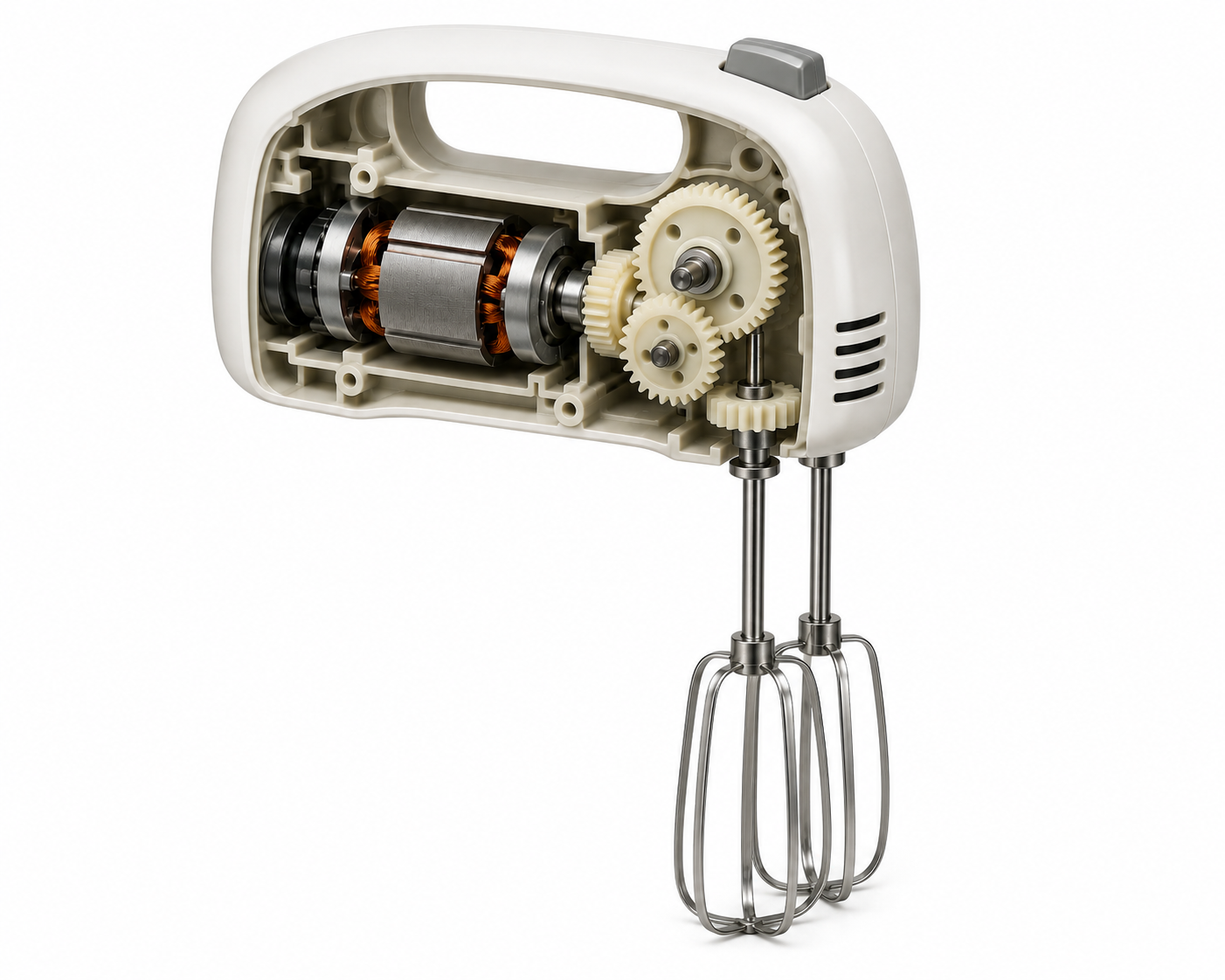
Real-life examples: Compound gear trains are found in car gearboxes, mechanical clocks, and hand-powered food whisks — anywhere a large speed change is needed in a small space.
Real-life examples
📌
Coming soon — gear-compound-real-life.png
Add to images/ folder.
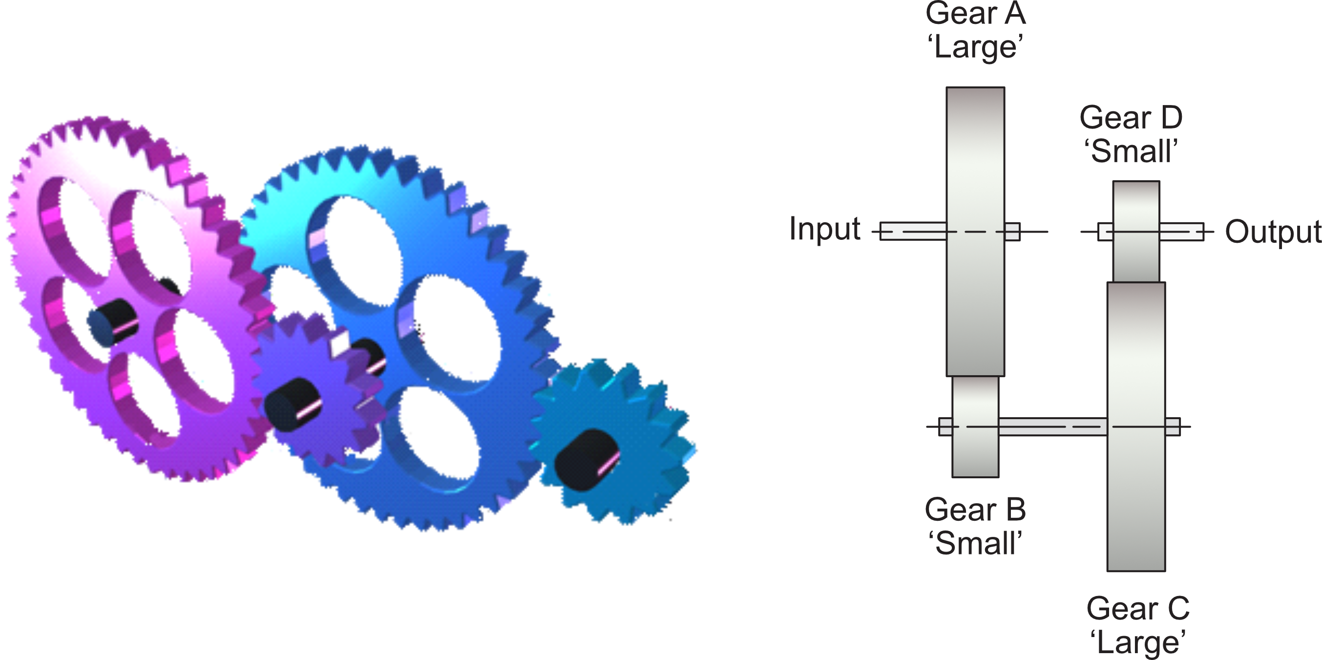
Compound gear train diagram
📌
Coming soon — gear-compound-plan.png
Add to images/ folder.
Calculating compound gear VR
Worked Example — Compound gear train
Input gear: 20 teeth. Large gear on intermediate shaft: 80 teeth. Small gear on intermediate shaft: 10 teeth. Output gear: 60 teeth. Input speed: 240 rev s−1.
The sim loads with the compound gear train from the worked example — a 20T driver, an 80T/10T intermediate pair, and a 60T output. Click ▶ RUN SIM and watch how the two stages of gearing multiply the speed reduction: the first pair gives VR = 4, the second gives VR = 6, and the overall result is VR = 24. Try replacing individual gears with different sizes to see how the total VR changes.
NoGrind Sim V1.2 — Peter Strain, Bearsden Academy
✏️ Task 5 — Compound gear calculations
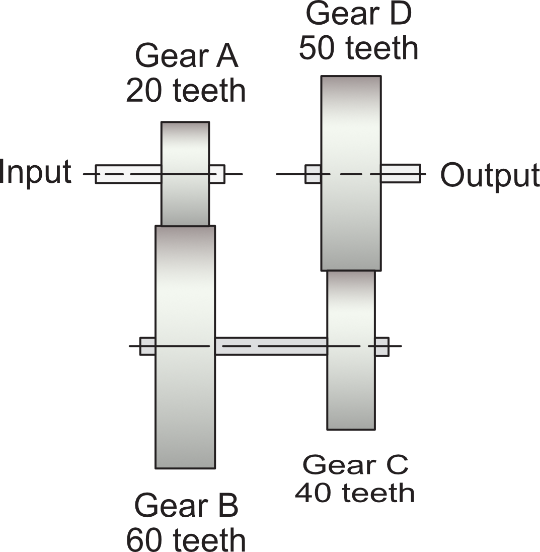
A compound gear train is driven by a motor at 1000 rev/min. Gear A = 20 teeth, Gear B = 60 teeth (on intermediate shaft with A), Gear C = 40 teeth, Gear D = 50 teeth (output).
📌
Diagram coming soon — task5-compound-diagram.png
Add this file to the images/ folder to display it here.
a) Calculate the total velocity ratio.
Working ✓ Saved
b) Calculate the output speed.
Working ✓ Saved
Using the NoGrind simulator, build a compound gear train using gears of 8, 16, 24 and 40 teeth that produces the greatest possible speed increase. Calculate the VR of your system.
Design and VR ✓ Saved
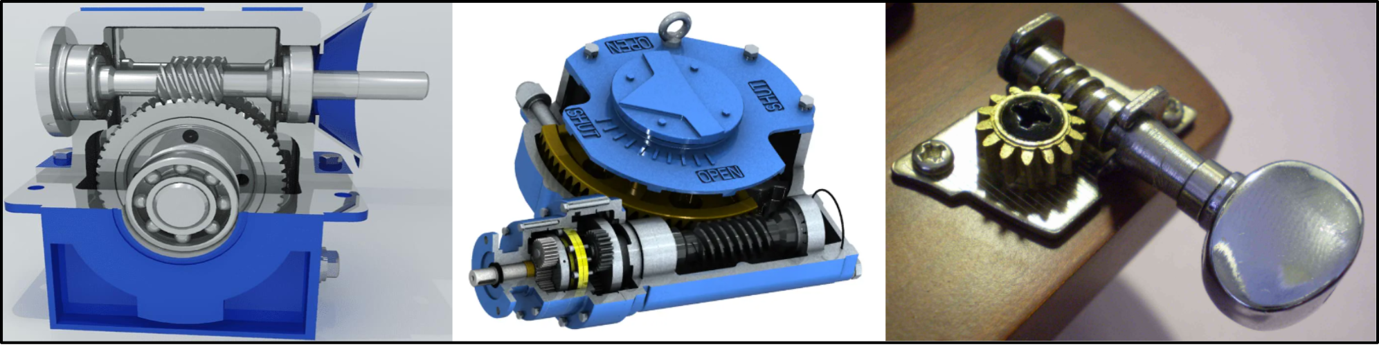
Section 6: Worm and Wheel
📚 Interesting — but not examined: This section does not appear in the N5 course specification or QS exams. It gives useful real-world context but you do not need to learn it for assessment.
A worm gear is another way to achieve large speed reductions. The worm looks like a screw thread and is fixed to the driver shaft. It meshes with a worm wheel fixed to the driven shaft, which runs at 90° to the driver shaft.
📌
Diagram coming soon — worm-gear-animation.gif
Add this file to the images/ folder to display it here.
Real-life examples: Worm gears are used in guitar tuning pegs, steering mechanisms, and conveyor belt drives — any application that needs a large speed reduction in a compact space, and where the drive should be self-locking (the worm wheel cannot back-drive the worm).
📌
Diagram coming soon — worm-gear-real-life.png
Add this file to the images/ folder to display it here.
For calculation purposes, treat the worm as a single-tooth gear. One full rotation of the worm advances the worm wheel by exactly one tooth.
Worked Example — Worm and wheel
A worm meshes with a 30-tooth worm wheel. The motor rotates at 100 rev s−1. Calculate the output speed.
Click ▶ RUN SIM to start. The sim loads with a prebuilt worm and wheel. Observe how one full rotation of the worm advances the wheel by exactly one tooth. Adjust the number of teeth on the worm wheel and observe the effect on output speed.
NoGrind Sim V1.4.1 — Peter Strain, Bearsden Academy
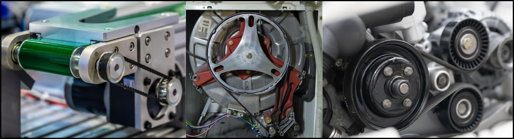
Section 7: Belt Drives
📚 Interesting — but not examined: This section does not appear in the N5 course specification or QS exams. It gives useful real-world context but you do not need to learn it for assessment.
Belt drives transmit rotary motion between shafts that may be far apart. A belt wraps around two or more pulleys — thin metal discs with a groove cut into the rim. The belt is tensioned by pulling one pulley out and locking it in place.
Unlike meshing gears, belt drives do not reverse the direction of rotation. To reverse direction, the belt must be crossed between the pulleys.
Real-life examples: Belt drives are used in washing machines, lathes, air compressors and car alternators — wherever a smooth, quiet drive is needed between shafts that are too far apart for gears.
📌
Diagram coming soon — belt-open-crossed.png
Add this file to the images/ folder to display it here.
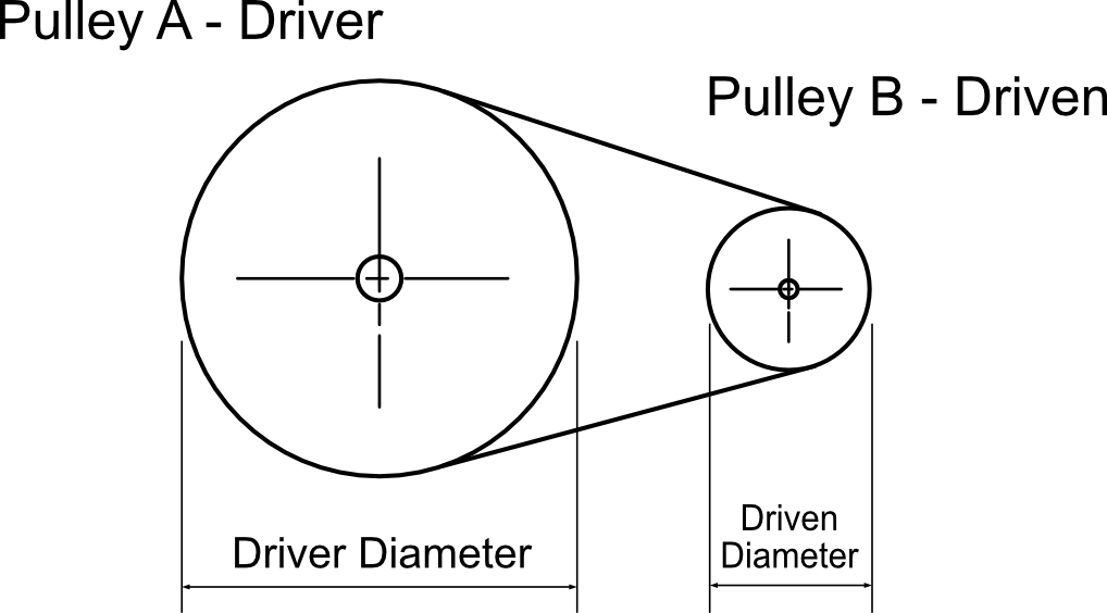
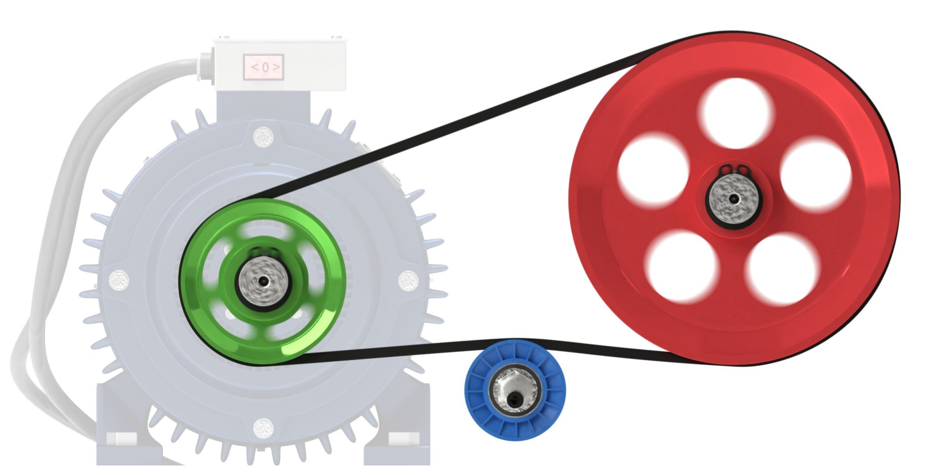
Belt drive calculations
Belt drives also enable rotation speeds to be changed. The calculations are similar to gear trains but rather than using numbers of teeth, pulley diameters are used.
📌
Diagram coming soon — belt-pulley-diagram.png
Add this file to the images/ folder to display it here.
Driver pulley diameter: 120 mm. Driven pulley diameter: 40 mm. Input speed: 1200 rev/min.
1
VR: 40 ÷ 120 = 1/3 (or 1:3)
2
Output speed: 1200 ÷ (1/3) = 3600 rev/min (speed increase because driven pulley is smaller)
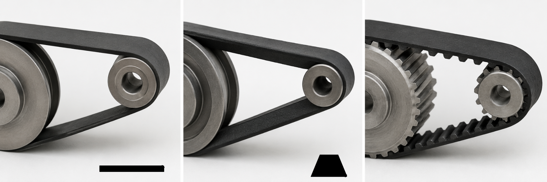
Types of belt
Flat belt
Simple rectangular cross-section
Runs on flat-faced pulleys
Inexpensive and easy to replace
No lubrication needed
Suitable for light loads and high speeds
Can slip under heavy loads
V-belt
Wedge-shaped cross-section that grips the pulley groove
Transmits more torque than a flat belt due to the wedging action
Multiple V-belts can be used side by side where extra power is needed
Less likely to slip than a flat belt
Absorbs shock loads without damage
Widely used in industrial machinery and car engines
Toothed (timing) belt
Interlocking teeth prevent any slipping
Maintains precise timing between driver and driven shafts
Used where slippage would cause damage — e.g. car engine timing belt
Quiet and low maintenance in operation
More expensive than flat or V-belts
Cannot absorb shock loads — teeth can shear if overloaded
📌
Photo/diagram coming soon — belt-types-photo.png
Add this file to the images/ folder to display it here.
Jockey pulley
A jockey (tensioner) pulley is a spring-loaded pulley used to keep the belt correctly tensioned. Too slack and the belt slips; too tight and the bearings wear out.
📌
Diagram coming soon — belt-jockey-pulley.png
Add this file to the images/ folder to display it here.
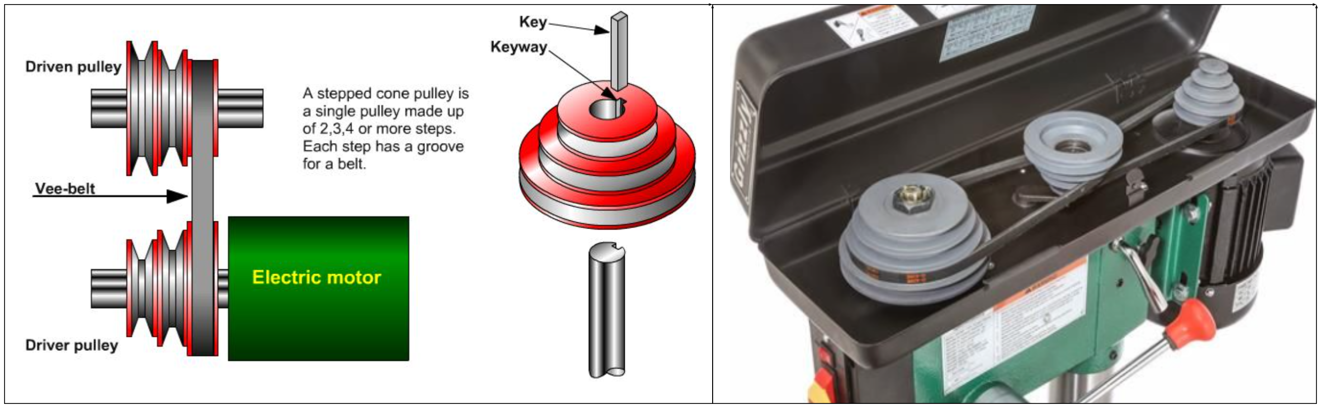
Stepped-cone pulleys
A variety of output speeds can be achieved without changing pulleys by using stepped-cone pulleys — a series of pulleys of different diameters fixed to the same shaft. Moving the belt to a different step changes the speed ratio.
Real-life example: Stepped-cone pulleys are used on pillar drills and some lathes to select different cutting speeds depending on the material being worked.
📌
Diagram coming soon — belt-stepped-cone.png
Add this file to the images/ folder to display it here.
✏️ Task 6 — Belt drive calculations
Calculate the missing quantities. In each case the left pulley is the driver.
a) Driver diameter: 40 mm, 1200 rev/min. Driven diameter: 80 mm. Calculate the output speed and VR.
Working ✓ Saved
b) Driver diameter: 60 mm, 900 rev/min. Output speed: 300 rev/min. Calculate the driven diameter and VR.
Working ✓ Saved
c) Driven diameter: 120 mm, 500 rev/min. VR = 3. Calculate the driver diameter and input speed.
Working ✓ Saved
Research: Name three real-world machines or systems that use belt and pulley drives.
Answer ✓ Saved
Sketch or describe a belt drive system that produces a decrease in speed with a change in direction of the driven pulley.
In the Components panel, open Chain Drive & Belt Drive and click Add Belt Drive. The belt snaps to an existing axle and generates a second pulley automatically. Select each pulley and adjust its diameter in the Properties panel. Run the simulation to see the speed and direction labels.
NoGrind Sim V1.2 — Peter Strain, Bearsden Academy
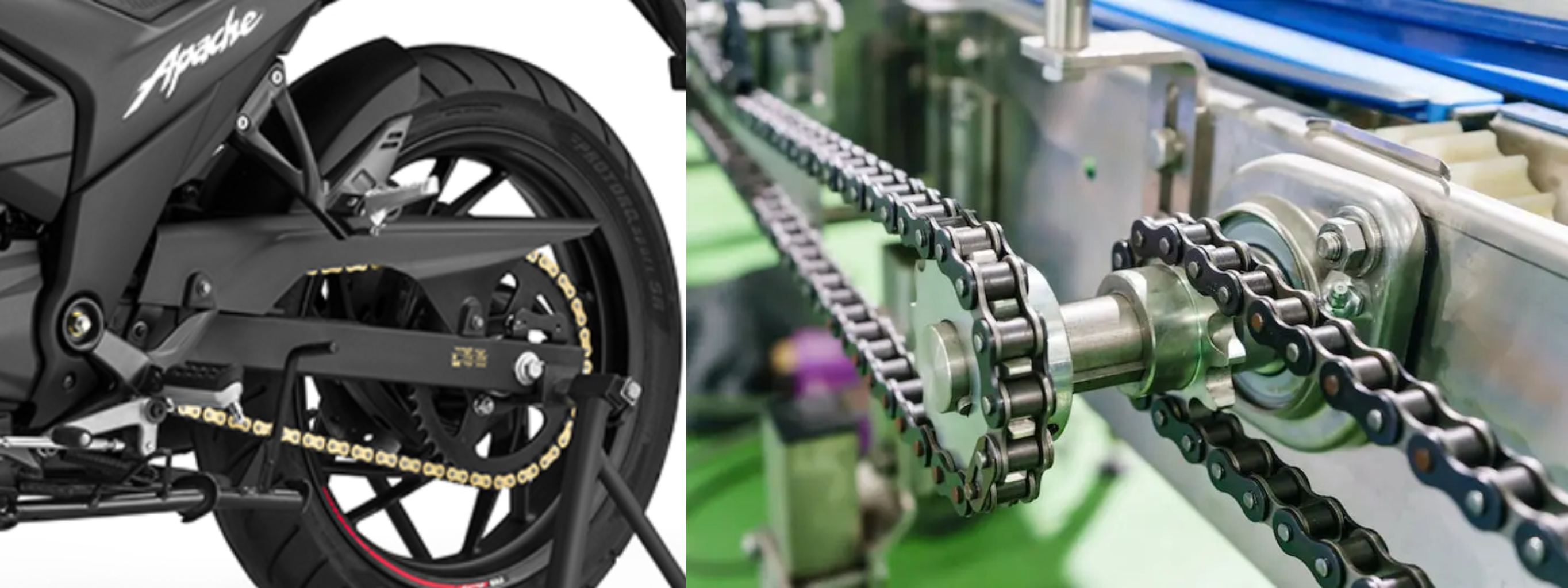
Section 8: Chain Drives
📚 Interesting — but not examined: This section does not appear in the N5 course specification or exams. It gives useful real-world context but you do not need to learn it for assessment.
Where large forces must be transmitted with no slippage, a chain drive is used. Instead of a pulley, a toothed wheel called a sprocket drives a chain, which in turn drives another sprocket. Chain drives do not slip.
Real-life examples: Bicycles, motorcycles, and industrial conveyor systems all use chain drives where a positive, non-slip drive is essential.
Advantages of chain drives
Very strong — will not slip under normal conditions
Transmits large forces reliably
Positive drive — no loss of motion
Disadvantages of chain drives
Must be oiled regularly
Chain and sprockets prone to wear
More expensive than belt drives
Noisier than belt drives
📌
Diagram coming soon — chain-bicycle.png
Add this file to the images/ folder to display it here.
For every 1 revolution of the pedals, the wheel turns 6 times — a speed increase.
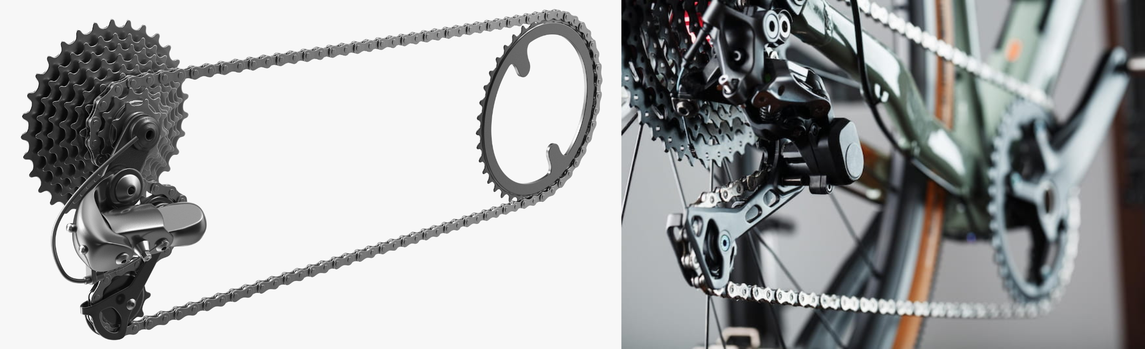
📚 Interesting — but not examined: The following section on Derailleur gears gives useful real-world context but does not appear in the N5 course specification or QS exams. Read it for interest but you do not need to learn it for assessment.
Derailleur gears
Racing bikes and mountain bikes use Derailleur gears — a spring-loaded jockey wheel that keeps the chain tensioned while allowing it to be moved between different sprockets on a cassette (rear hub) and different chainrings (front). This gives a wide range of gear ratios for different terrains.
📌
Diagram coming soon — chain-derailleur.png
Add this file to the images/ folder to display it here.
✏️ Task 7 — Chain drive calculations
a) Driver sprocket: 48 teeth, 60 rev/min. Driven sprocket: 16 teeth. Calculate the output speed and VR.
Working ✓ Saved
b) Driver: 24 teeth, 200 rev/min. Output speed: 50 rev/min. Calculate the number of teeth on the driven sprocket and the VR.
Working ✓ Saved
A cyclist wants to go faster suddenly and puts extra force into the pedals. Explain why the chain must not slip for this to work, and what would happen if it did.
In the Components panel, open Chain Drive & Belt Drive and click Add Chain Drive. Adjust the number of teeth on each sprocket in the Properties panel. Run the simulation and compare the speed labels for different sprocket sizes.
NoGrind Sim V1.2 — Peter Strain, Bearsden Academy
Section 9: Converting Motion
Many mechanisms involve changing one type of motion into another. For example, the rotary motion of a pillar-drill handle is changed to the linear motion of the drill bit moving down.
Cams
📚 Interesting — but not examined: Cams do not appear in the N5 course specification or QS exams. This section gives useful real-world context but you do not need to learn it for assessment.
A cam is a specially shaped piece of metal or plastic that converts input rotary motion into output oscillating or reciprocating motion. The cam works by guiding a follower held against it by its own weight or a spring.
There are several types of cam — each producing a different pattern of follower movement:
Add this file to the images/ folder to display it here.
Circular (eccentric) cam — produces a smooth, continuous rise and fall of the follower
Pear-shaped cam — has a dwell period (the follower is stationary for part of the revolution) followed by a rapid rise and fall. Used on car camshafts to operate engine valves.
Heart cam — designed to produce a uniform, constant rise in the follower
Drop (snail) cam — follower rises gradually then drops suddenly; used in alarm clock mechanisms
Real-life examples: Cams are used in car engine camshafts to open and close valves, in sewing machines to create stitch patterns, and in some music boxes.
📌
Animation coming soon — cam-real-life.gif
Add this file to the images/ folder to display it here.
📚 Interesting — but not examined: The cam part names below (crown, heel, dwell, stroke) give useful context but are not required knowledge for the N5 exam. You do not need to memorise these terms for assessment.
Cam terminology
Crown — the highest point of the cam profile (follower at maximum height, valve fully open)
Heel — the lowest point of the cam profile (follower at rest, valve closed)
Dwell period — the part of the cam rotation where the follower is stationary
Stroke — the distance between the crown and heel (= the distance the valve opens)
✏️ Task 8 — Cams
A pear-shaped cam and follower forms a simple locking mechanism. Name the cam (A) and the follower (B). How much of a turn does the wheel make to push the lock-bolt closed? Describe why the spring is needed.
Answer ✓ Saved
A cam on a car engine valve mechanism turns half a revolution from the position shown below (follower at heel). What distance does the valve move? (The stroke of the cam is 8 mm.)
Answer ✓ Saved
Section 10: Crank and Slider
📚 Interesting — but not examined: This section does not appear in the N5 course specification or QS exams. It gives useful real-world context but you do not need to learn it for assessment.
A crank-and-slider mechanism converts between rotary and reciprocating motion. The crank rotates while the slider (piston) reciprocates in a straight line. The longer the crank, the further the slider moves.
Add this file to the images/ folder to display it here.
Real-life examples: Car engines (piston to crankshaft), power hacksaws, reciprocating pumps and steam engines all use the crank-and-slider mechanism.
The crank-and-slider is used in two main ways:
Reciprocating → Rotary: Car engines — pistons connected to a crankshaft by connecting rods. As pistons move down in sequence they keep the crankshaft turning.
Rotary → Reciprocating: Power hacksaw — a motor drives a crank connected to a saw frame that slides back and forth on an arm.
✏️ Task 9 — Crank and slider
A crank-and-slider mechanism is used in a fabric-testing machine. The crank is 30 mm long. A wire brush is attached to the slider.
a) What is the distance from A (one end of slider travel) to B (the other end)?
Answer ✓ Saved
b) What effect does the wire brush have on the fabric?
Answer ✓ Saved
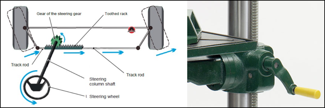
Section 11: Rack and Pinion
📚 Interesting — but not examined: This section does not appear in the N5 course specification or QS exams. It gives useful real-world context but you do not need to learn it for assessment.
A rack and pinion mechanism converts rotary motion to linear motion (or vice versa). A round spur gear (the pinion) meshes with a flat toothed bar (the rack).
Real-life examples: Rack and pinion mechanisms are used in car steering systems, pillar drills, camera tripods and stairlift tracks.
📌
Diagram coming soon — rack-pinion.png
Add this file to the images/ folder to display it here.
There are three ways a rack and pinion can be used:
In the Components panel, open Rack and Pinion and click Add Rack & Pinion. The rack snaps to an existing axle. Run the simulation — the rack physically moves left and right. Note that a Safety Cutoff triggers when the rack reaches its limit; reverse the motor to continue.
NoGrind Sim V1.2 — Peter Strain, Bearsden Academy
✏️ Task 10 — Rack and pinion
A rack is 200 mm long with a pitch (tooth spacing) of 2 mm. It meshes with a pinion that has 20 teeth.
a) If the pinion rotates one full revolution, how far does the rack move? (Hint: distance = number of teeth × pitch)
Working ✓ Saved
b) How many complete revolutions of the pinion are needed to move the rack from one end to the other?
Working ✓ Saved
Draw the symbols for the following mechanisms: simple gear train, belt drive, chain drive, rack and pinion.
Sketches ✓ Saved
💾 Answers saved automatically in this browser on this device.