Section 1: What are Pneumatics?
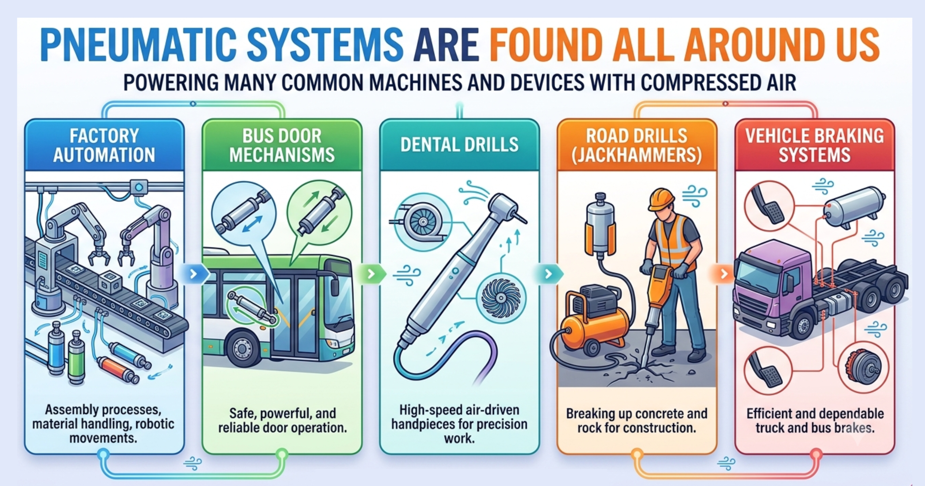
Pneumatics is the use of pressurised air to do mechanical work. A compressor draws in air from the atmosphere and compresses it to a higher pressure. This compressed air is stored and then controlled to produce linear or rotary movement. Pneumatic systems are found all around us — in factory automation, bus door mechanisms, dental drills, road drills, and vehicle braking systems.
Advantages of pneumatic systems
Pneumatic systems offer several advantages over hydraulic or electrical systems: compressed air is non-flammable and safe to use in hazardous environments; the components are relatively low-cost; speed is easy to adjust using flow control valves; and any leaks result only in air escaping rather than fluid spillage.
Disadvantages
Air is compressible, so precise positioning can be difficult. Pneumatic systems can be noisy, and energy is lost as heat when air is compressed. A compressor and air supply are always required.
1a. Give three examples of pneumatic systems you might encounter in everyday life. For each one, describe what work the compressed air is doing.
1b. Explain one advantage and one disadvantage of using a pneumatic system compared to an electric motor for a door-opening mechanism.
Section 2: Pneumatic Components and Symbols
All pneumatic circuits are drawn using standard symbols. You need to be able to recognise each component symbol, know its function, and identify how it is connected in a circuit. The No Pressure simulator will be very useful to support you in doing this — use it alongside these notes to see each component in action.
Main air supply and exhaust
Every pneumatic circuit needs a main air supply — the pressurised air from the compressor. In circuit diagrams this is shown as a circle with a dot in the centre. Exhaust is where used air vents to atmosphere after passing through the circuit; it is shown as an open triangle pointing away from the circuit.


Directional control valves
Directional control valves direct main air to different parts of the circuit. They are described by the number of ports (connections) and the number of states (positions the valve can be in).
The best way to understand valves is to experiment with one in the simulator below — operate it and watch what happens to the air flow. The explanation of how to read the symbol will make much more sense once you have seen it in action.
3/2 valve — used with single acting cylinders
A 3/2 valve has 3 ports and 2 states. Port 1 = main air in; port 2 = air to/from cylinder; port 3 = exhaust. In the normal state, the cylinder is connected to exhaust. When actuated, main air flows through to the cylinder.


5/2 valve — used with double acting cylinders
A 5/2 valve has 5 ports and 2 states. Port 1 = main air; port 2 = outstroke side of cylinder; port 3 = exhaust (outstroke side); port 4 = instroke side of cylinder; port 5 = exhaust (instroke side). Switching the valve reverses which side of the cylinder receives main air.


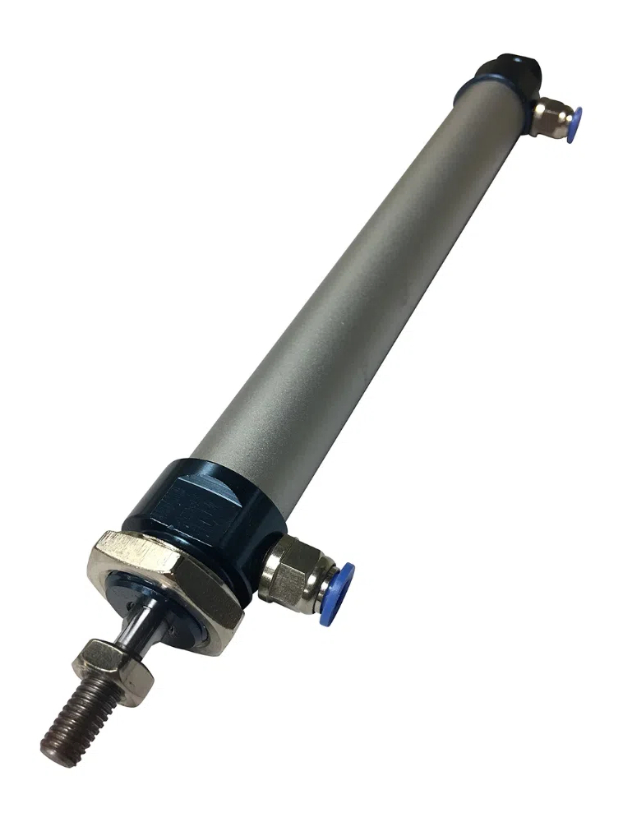
Cylinders
Single acting cylinder (SAC): Main air causes the outstroke (extension of the piston rod). A spring returns it when pressure is released. SACs are used where force is only needed in one direction.
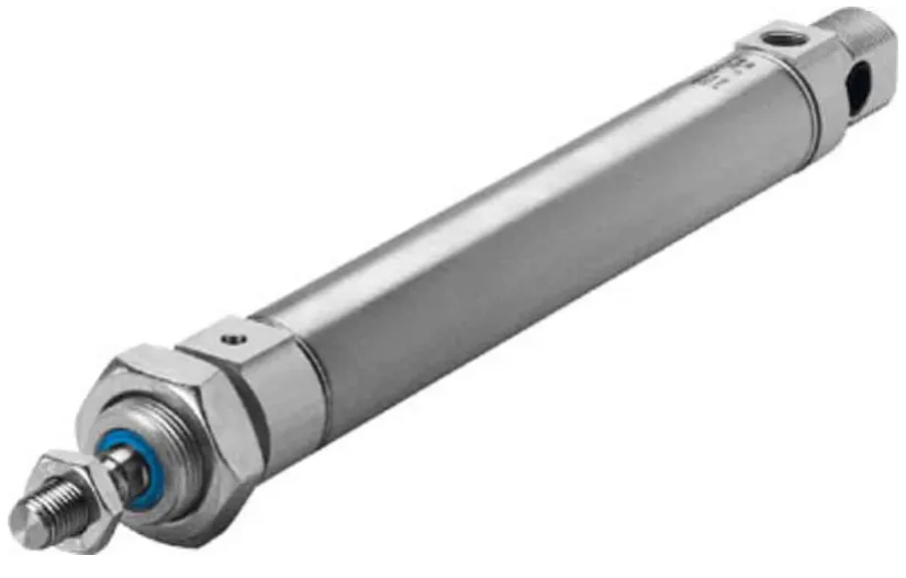
Double acting cylinder (DAC): Main air drives both the outstroke and instroke via two ports. DACs provide force in both directions.

Valve actuators
A valve can be switched into its actuated state in different ways. You need to know the following types:
- Push-button: The operator presses a button to switch the valve manually.
- Roller: A roller on the end of the valve is tripped by the cylinder rod or a moving part. Used as a limit valve to detect when a cylinder has reached the end of its stroke.

- Lever: A lever arm trips the valve — similar to a roller but operated by a flat surface rather than a roller.
- Plunger: A flat-ended plunger is pushed to switch the valve — often used as a limit valve.
- Pilot (main air): A main air pressure signal from another part of the circuit acts on the valve to switch it. Used in semi-automatic and automatic circuits where one valve triggers another. Note: this requires main air pressure to operate.
- Diaphragm: Works on a similar principle to a pilot actuator but operates on much smaller changes in pressure — a low-pressure signal is enough to switch the valve.
- Solenoid: An electrical signal energises a coil which switches the valve. This allows electronic systems and microcontrollers to control pneumatic circuits.


Solenoid circuit example
A solenoid-actuated valve is connected to an electrical control system (such as a microcontroller or PLC). When the control system sends an electrical signal to the solenoid, it switches the valve and main air flows to the cylinder. When the electrical signal is removed, the spring returns the valve to its normal state and the cylinder instrokes. This allows a pneumatic circuit to be controlled entirely by software or by electronic sensors such as light gates or pressure switches.

Restrictors
Restrictors limit the flow rate of air, controlling the speed of a cylinder. There are two types:
Restrictor: Reduces flow equally in both directions — slows the cylinder on both outstroke and instroke.
Uni-directional restrictor (UDR): Allows free flow in one direction and restricted flow in the other — so outstroke and instroke speeds can be controlled independently.


Shuttle valve
A shuttle valve has two inlets and one outlet. Main air entering either inlet pushes the ball across to seal the other inlet and passes through to the outlet. This means main air passes through if input A or input B is pressurised. If main air enters both inlets simultaneously, the ball remains in its current position and main air still passes through to the outlet.

T-piece (air supply splitter)
A T-piece splits one main air supply into two branches, allowing the same supply to feed two different parts of a circuit simultaneously.
2a. Use the No Pressure simulator or physical components to connect a 3/2 push-button valve and a single acting cylinder. Operate the valve and observe how main air and exhaust flow through the circuit. Describe what you observe.
2b. Describe what happens to the flow paths inside a 5/2 valve when it changes state. Which ports carry main air and which become exhausts in each state?
2c. Explain the difference between a pilot actuator and a solenoid actuator on a valve. In which type of circuit would each be used?
2d. Explain the difference between a restrictor and a uni-directional restrictor (UDR). Give an example of when you would use each type.
Section 3: Single Acting Cylinder Circuit
The simplest pneumatic circuit uses a single acting cylinder (SAC) controlled by a 3/2 push-button valve. When the button is pressed, main air flows to cause the outstroke. When released, the spring in the valve returns it to its normal state, exhausting the cylinder so the cylinder spring can instroke the rod.
3a. Use the No Pressure simulator or physical components to build the SAC circuit. Operate the push-button valve and describe what happens. In your answer, describe the state of the valve and what the cylinder does when the button is pressed and when it is released.
3b. Describe what happens to the cylinder if the push-button valve is held down for longer. What determines the maximum force the cylinder can produce?
Section 4: Double Acting Cylinder Circuit
A double acting cylinder (DAC) requires main air to be directed to either side of the piston, while the opposite side exhausts. This is controlled by a 5/2 directional control valve. Changing the state of the valve reverses the direction of the cylinder.
4a. Use the No Pressure simulator or physical components to build the DAC circuit. Operate the 5/2 valve in both directions. Describe what you observe and explain how the DAC differs from the SAC circuit you built in Task 3.
4b. A DAC circuit has its 5/2 valve in the normal state. Describe what the cylinder is doing. Explain what happens to the cylinder when the valve changes to its actuated state.
Section 5: T-Piece — Splitting the Air Supply
A T-piece connector allows one main air supply to feed two or more separate branches of a circuit simultaneously. Both branches receive the same supply pressure. T-pieces are used when a single air source needs to power multiple cylinders or valves at the same time.
5a. Use the simulator or physical components to build a circuit using a T-piece to operate two cylinders from the same main air supply. Describe what you observe. What happens to each cylinder when the valve is operated?
5b. Give one example of a practical application where a T-piece would be useful in a pneumatic circuit.
Section 6: Shuttle Valve
A shuttle valve allows a cylinder to be operated from two separate control valves — main air from either valve can cause the outstroke. This is useful when a machine needs to be operated from two different locations.
Inside the shuttle valve is a small ball. When main air enters from one inlet, it pushes the ball to seal the other inlet and passes through to the outlet. If main air enters the other inlet instead, the ball moves across and the same thing happens. If main air enters both inlets at the same time, the ball remains in its current position and main air still passes through to the outlet.
6a. Explain how a shuttle valve works. What happens inside the valve when main air enters from one inlet? What happens if main air enters from both inlets at the same time?
6b. A press in a workshop can be dangerous to operate with one hand. Describe how a shuttle valve could be used as part of a two-handed safety circuit.
Section 7: Air Bleed (Diaphragm) Circuit
An air bleed circuit uses a diaphragm-actuated 3/2 valve and works differently from all the circuits you have seen so far — instead of pressing a valve to supply air, this circuit works by blocking a small continuous flow of air.
How it works
In the normal state, main air constantly bleeds to atmosphere through a small hole in the circuit (the bleed point). Because this air is always escaping, there is never enough pressure to act on the diaphragm — the valve stays in its normal state and the cylinder remains instroked.
When an object or a finger covers the bleed hole, the escaping air is blocked. Pressure immediately builds up behind the diaphragm. Once it reaches the switching threshold, the diaphragm switches the 3/2 valve, main air flows to the cylinder, and the cylinder outstrokes.
As soon as the obstruction is removed, air bleeds away again, pressure drops, the diaphragm releases, and the valve spring returns it to its normal state — causing the cylinder to instroke.

7a. Explain how an air bleed circuit works. In your answer, describe what happens at the bleed point when it is open, and what happens when it is blocked.
7b. Describe one practical application of an air bleed circuit. Explain what causes the bleed to be blocked in your example and what action this triggers.
7c. State one key difference between an air bleed circuit and a standard push-button SAC circuit.
Section 8: Speed Control — Restrictors
The speed of a pneumatic cylinder can be controlled by limiting the flow rate of air using a uni-directional restrictor (UDR).
Meter-in: The restrictor is placed on the main air supply side. It limits the main air flowing into the cylinder, slowing the stroke.
Meter-out: The restrictor is placed on the exhaust side. It limits the air flowing out to exhaust. This gives smoother speed control and is preferred because the back-pressure helps support the load.
8a. Use the simulator or physical components to build a circuit with a UDR. Adjust the restrictor and observe how the cylinder speed changes. Explain the difference between meter-in and meter-out speed control. Which method should always be used in pneumatics and why?
8b. A packaging machine uses a SAC to push items along a conveyor. The operator wants the outstroke to be slow but the instroke to be quick. Explain where a uni-directional restrictor (UDR) should be placed and how it should be oriented to achieve this.
Section 9: Semi-Automatic Circuit
A semi-automatic circuit requires a manual input to start each cycle, but part of the operation happens automatically. A typical arrangement uses a DAC, a 5/2 valve with pilot actuators, and a roller spring-return valve triggered by the cylinder rod at the end of its outstroke.
The operator presses a start button which sends a pilot signal (main air pressure) to change the state of the 5/2 valve. Main air causes the DAC to outstroke. At the end of the outstroke the rod actuates a roller spring-return valve, which sends a pilot signal to return the 5/2 valve to its normal state. Main air now drives the instroke while the outstroke side exhausts. The circuit then waits for the next button press.
9a. Describe the complete operating cycle of a semi-automatic pneumatic circuit. Include reference to: the pilot signal, how main air causes the outstroke, what triggers the instroke, and what happens at the end of the cycle.
9b. Explain the difference between a manual circuit and a semi-automatic circuit. Give one advantage of using a semi-automatic circuit in a production environment.
Section 10: Fully Automatic Circuit
A fully automatic circuit repeats its cycle continuously without any manual input after the initial start signal. A second limit valve at the instroked position sends a pilot signal to trigger the next outstroke automatically, so the cylinder cycles back and forth until the main air supply is cut off.
10a. Explain the role of each limit valve in a fully automatic circuit. What would happen if the limit valve at the retracted position were removed?
10b. A fully automatic circuit is used in a bottling plant to cap bottles on a conveyor. Describe how the circuit could be modified to allow an operator to stop the machine safely at the end of a cycle (not mid-stroke).
Section 11: Time Delay Circuit
A time delay valve introduces a controllable delay between an input signal and an output action. It consists of a uni-directional restrictor feeding a reservoir, which builds up main air pressure slowly until it is high enough to pilot (switch) a 3/2 output valve.
By adjusting the restrictor, the fill time of the reservoir — and therefore the length of the delay — can be changed. Increasing the size of the reservoir will also increase the delay time, as more volume must be filled before the pilot threshold is reached. When the input signal is removed, the reservoir vents quickly back through the UDR and the timer resets immediately.
11a. Describe how a pneumatic time delay circuit produces a time delay. Include reference to the restrictor, reservoir, and pilot-operated output valve.
11b. A time delay circuit is set to delay for 3 seconds. An engineer wants to increase the delay to 8 seconds. Explain two ways this could be achieved.
11c. Use the simulator or physical components to build a time delay circuit. Adjust the UDR to make the delay longer and shorter. Describe what you observe and explain why adjusting the restrictor changes the delay time.
11d. Describe one practical application of a time delay circuit in an industrial or domestic context. Explain what the delay achieves in your chosen example.